
3D printed compressed air tank
To readers redirected from hackaday.com
There has been a mash-up of informations on the article you came from. For the sake of better understanding, let us provide you with some context and discuss a few details.
We are experimenters building robots in a club, we do not build commercial air tanks. We take part in the Eurobot contest every year, and one action to be performed this year could be nicely executed with the help of pneumatics and compressed air stored in a tank placed in one of our robots. Our requirement was to have as big as a tank to fit in a prismatic rectangular space. A cylinder would not have done the job properly and would not have been innovative. A 3D-printed air tank would do both, so we tried a few ideas.
Then, to address criticism emitted in the comment section, 4.0 bar = 58 psi and 6.5 bar = 94 psi, these are low pressures. 6.5 bar was the pressure we subjected our prototypes to, whereas 4.0 bar was the maximum pressure the tank would have to endure during contest use, our security factor there is at the very least 1.6 on the prototype used in our robot, which would most certainly not be tolerated on a commercial product, but enough for our specific application. Then, the tank is enclosed in our robot behind 2 mm thick (0.078 in) aluminium panels. Shrapnel would not be able to escape the robot and cause injuries any rupture had occurred.
Finally, we use PLA filament to 3D-print our parts, not PVC as some readers understood. We do not understand why our blog post somehow ended up being embedded in a post on hackaday.com relating events regarding the safety of PVC pipes use for compressed air.
In order to perform the funny action for Eurobot 2016, we considered a pneumatic umbrella and needed to have a reservoir of compressed air in our robot.
The tank would need to sustain prolonged operation at 4 bar and the pneumatic system as a whole would have to be airtight enough so that a funny action triggered 60 minutes after refilling the tank would still be successful.
Idea doubled by opportunity
3D printing allows for fast prototyping at low costs and super low iteration cycle times. Once you get used to printing parts and you have to test a new idea, you just end up doing it without a second thought. At CVRA we 3D print main mechanical internal parts as well as cosmetic external bodyshells. We can make stiff parts as well as bendable ones. Pretty much every idea we have is a candidate for 3D printing at some point.
So… I hear you have to use a compressed air tank for your pneumatic system, right? What if you just… 3D print it?
After all 4 bar is not such a high pressure. We are routinely using PLA filament and this material has a rather high yield tensile strength. Doing a quick “back of the envelope” calculation indicates wall thickness can be pretty low.
Prototype #1: excitement
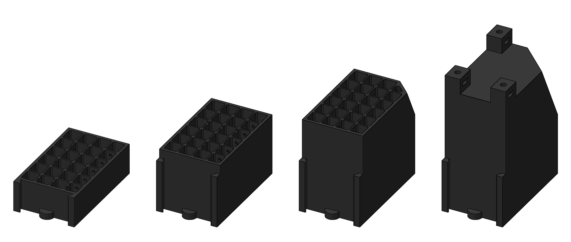
Our first attempt was a 40x40x40mm air tank exported in STL as a solid and printed with a wall thickness of 4 layers and 20% infill. A 3mm hole was drilled on the side, and deep drilling the tank opened a clear venting channel within the infill structure. The test was a direct success. The tank was able to sustain pressures up to 6.5 bar without a hitch and be airtight enough to successfully deploy the pneumatic umbrella after a 1-hour delay.
Prototype #2: adrenaline
Then came the time for a larger tank version our robot would accommodate, ramping up in volume from 40x40x40mm to 65x40x80mm, a roughly +225% increase, leaving infill aside, opting for a 6-layer wall thickness and having an internal support helping with the leveling of the innermost layer of the top wall during 3D printing.
The tank exploded into pieces just centimeters to my face when subjected to 5.5 bar pressure.</p> I was wearing thick clothing and took the precaution to hide my face behind my arm, so nothing happened to me. But this is a clear reminder things can go wrong with only 4 bar of pressure. (Actually 2 bar are more than enough to do nasty damage. As an experiment we made a pointy steel javelin whose ejection velocity from a 6mm diameter pneumatic cylinder was really nasty enough any interference with human flesh had occurred.) </p>
- Rule #1: wear protective glasses when subjected to even remotely possible projections.
- Rule #2: hide behind a protection wall when things can potentially explode.
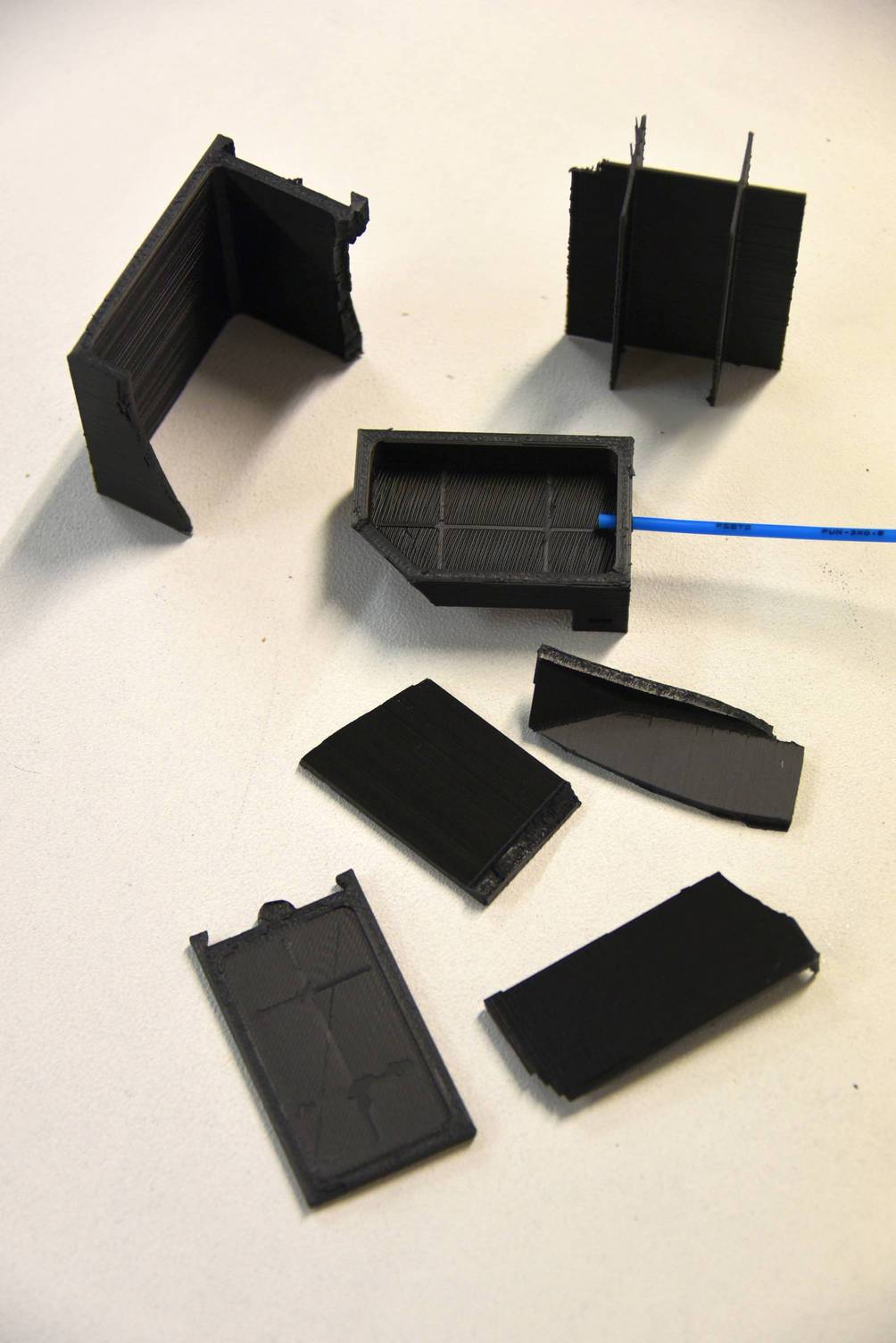
This is a cross-section view of the faulty design. The internal structure is not bound to the walls.
It is supposed the pressure inside the tank inflated the walls enough to accentuate stress concentration at the inner corners and to cause one of them to yield. The rest was a chain reaction resulting in a handful of fragments flying across the shop.</p>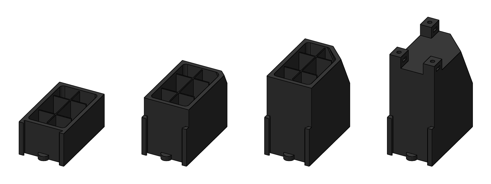
Prototype #3: production model
External features remain the same as for prototype #2 since the function and bulk volume have to be maintained. Changes are found inside. End-filleted ribs fill the inside of the tank, effectively preventing the walls from inflating. Those ribs essentially serve the same purpose as the infill structure found in prototype #1.
The tank lived past repeated 6.5 bar stress tests but leaked in the corners. Acrylic spray paint was applied to the outer surfaces and the tank now performs well. As a benchmark, well over 1 hour after an initial 3.6 bar fill, the funny action runs perfectly.
Although this tank is the one used on our 2nd robot, such an air-tightening solution is still not a fully satisfactory one, mostly because of the visible paint job.
Prototype #4: beyond
An additional test was performed to assess the ability of tire sealing compounds to render bleeding 3D printed tanks air-tight. Back to the basics, a 40x40x40mm tank with 3 layers of wall thickness was printed.
As expected, it did exhibit strong—and mesmerizing—bubbling from the corners when pressurized at 6.5 bar.
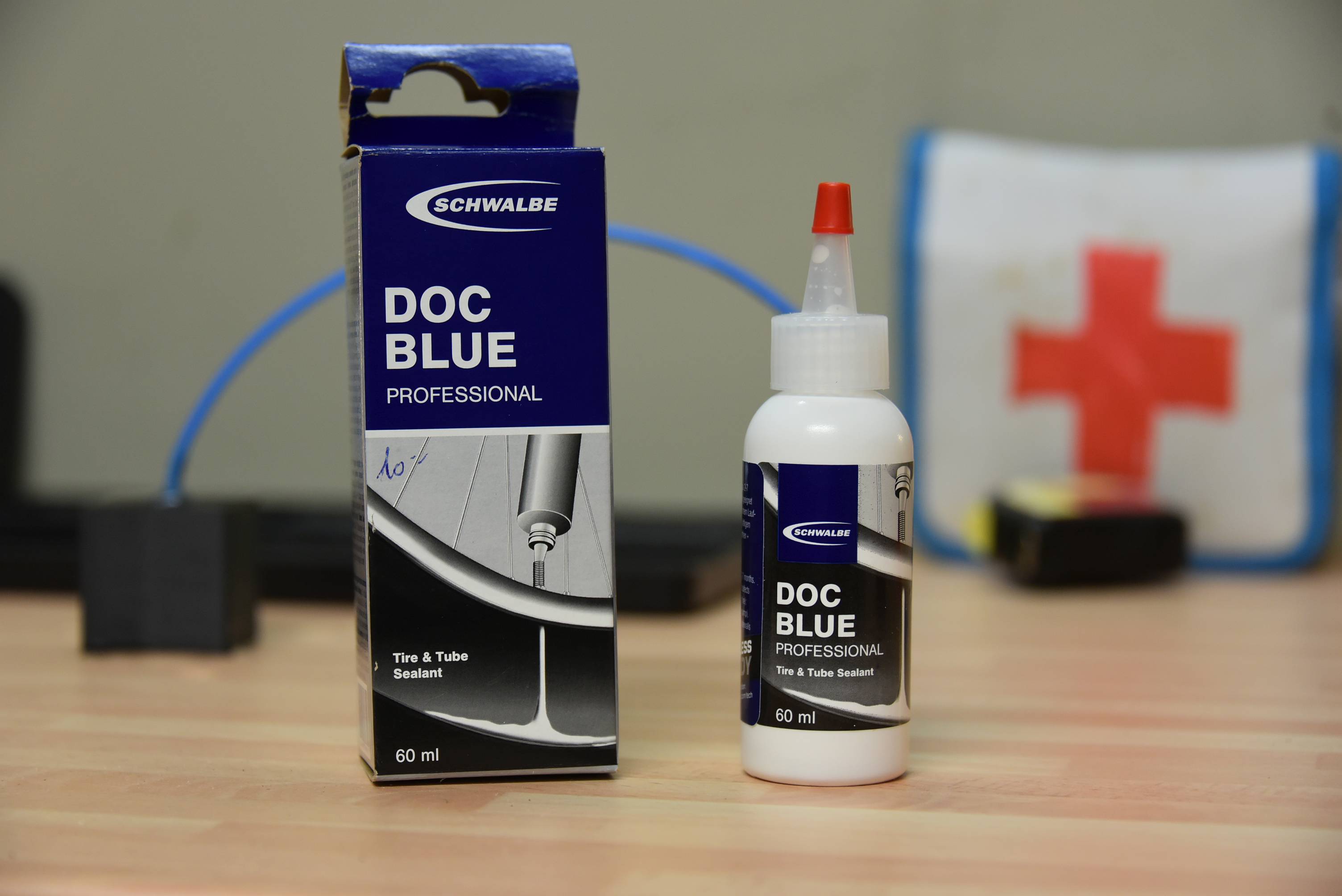
The tire sealing compound used was the following one.
After the internal surfaces of the tank were coated with liquid sealant and excess removed, we got a perfectly air-tight cube, apart from the inlet which initially leaked but soon was sealed too!
Other use cases
The air-tightening procedure described above will be applied to the internal suction channels of the hands of Debra 2016.